Development of a Grout Formulation for the Immobilization of the CR3 Reactor Vessel and Internals

Shane Prather, Dirk Bender, John Mayer
Orano DS, LLC
PRESENTING
March 14, 2024
Waste Management Symposia
ABSTRACT
The Orano Decommissioning Services (ODS) patented Optimized Segmentation process was implemented for the first time at the Crystal River Unit 3 (CR3) Accelerated Decommissioning Project in Florida. This process is an innovative approach for dismantling commercial and research nuclear reactors to reduce the volume of waste for disposal and the amount of segmentation work on the reactor structures. This process achieves substantial benefits in reducing the overall execution schedule and cost.
The segmented CR3 non-Greater Than Class C (GTCC) Internals Low Level Radioactive Waste components were repacked inside the Reactor Vessel (RV) using a precisely engineered placement of the contaminated and activated waste based on each piece’s characterization. The RV and repackaged internals were then immobilized in hardened grout specifically prepared to achieve the As Low As Reasonably Achievable (ALARA) goal and immobilize the Reactor Vessel Internals (RVI) inside the vessel. The solid, grout-filled RV packed with waste was subsequently segmented into three large sections (top, middle, bottom), consistent with the optimized waste distribution. Each section was packaged and shipped individually in a tailor-made container designed to safely transport and dispose of the waste in compliance with relevant regulations (NRC for Type B shipment, US Department of Transportation (DOT) for Industrial Package) and the disposal site’s Waste Acceptance Criteria.
ODS developed the grout formulation used to immobilize the structures inside the RV, and the vessel sections inside the transportation packages, through two years of design, testing, and qualification. The grout formulation was optimized to meet several objectives, critical functions, and associated technical requirements. The formulation ensured a minimum structural strength, a reasonably low density to maintain overall package weight limitation, and yet, at the same time, provide sufficient shielding benefit.
The grout development and testing work included four different phases: (1) grout formulation down-selection, (2) grout quality verification process, (3) grout production method, and (4) full-scale mockup grout delivery system demonstration. Ultimately, the final objectives accomplished were to guarantee that the process could be implemented and repeated with full control over the targeted grout technical requirements, and that we complied with the package regulatory safety requirements in the actual configuration of the grout delivery system and equipment, including with training and qualification of all the staff involved.
- The grout mixture viscosity was refined so that the loading could be staged outside of the radiologically controlled area. The grout was then pumped inside the RV to fill all the void spaces left around the repacked RVI. In view of optimizing the grout pouring process for a minimum execution time, the maximum pour height and the minimum set time were determined. Another critical parameter to be tightly controlled was the amount of porosity and void space left inside the packages once the immobilization was completed to ensure compliance with the Package License requirements, as hydrogen gas generation from bound and unbound water within the concrete matrix in the packages must be considered. Once cured, the grout formulation also needed to achieve the desired cutting performance during the segmentation of the encapsulated RV. The cut performance of the cured grout was verified before final approval of the grout formulation.
- A grout quality verification process was defined within the controlled production process adhering to ASTM and American Concrete Institute (ACI) testing standards and guides, respectively. Repeated sampling of the grout near its point of placement and testing for density and compressive strength, together with repeated testing of the quality of the slurry used in the grout production process, verified the quality of the placed grout.
- A continuous Low-Density Cellular Concrete (LDCC) production process was selected versus a batch production method. The production of this type of low-density grout requires three components: (1) slurry – a defined mix of water and Portland cement, (2) a foam concentrate product and (3) water and air. The grout is produced reliably with a cellular concrete continuous production machine. The machine mixes the products together at set ratios producing the desired grout.
- Design of the grouting operation started in October 2021, the testing and qualification phases were conducted in 2022, and grouting operations of the RV and packages were performed at the site in the spring and summer of 2023, respectively.
The three packages containing the grouted reactor structures are ready for off-site shipment and final disposal.
INTRODUCTION
Within the ODS patented Optimized Segmentation process, the filling of void space (volume not occupied by RVI) within the consolidated RV/RVI is a critical work evolution which ensures safe shipment and disposal of the three distinct RV/RVI segments by immobilizing the numerous RVI components with grout. This process creates a monolithic structure that can remain secure throughout the rigors of transportation. The void-filling medium must also satisfy a minimum air entrainment level to ensure that bound and unbound hydrogen cannot accumulate to unsafe levels which could pose a hazard, while also ensuring that package weight limits are not exceeded.
This scope of work is particularly challenging, as once the grout is placed in the RV and again, later in the large packages, it cannot be removed. Strict compliance with the requirements of the placed grout as defined in the Safety Analysis Report (SAR) needed to be ensured. Therefore, the processes of continuous grout production, delivery, and placement in the Reactor needed to be precisely engineered. Strict quality testing requirements were defined, resulting in a tightly controlled process. An extensive testing and training program needed to be developed to gain sufficient assurance of the practicability and executability of the process at CR3. There was no second attempt.
With these design requirements in mind, LDCC, AKA grout, was chosen to be the void-filling medium. The LDCC is produced with a proprietary cellular concrete continuous production machine known as a Foam Generator (FG), which injects pre-formed foam of a specific density into the outlet side of a progressive cavity positive displacement pump. The pump is responsible for pumping the slurry from the FG hopper into a delivery hose system. A multi-phase testing process was conducted to optimize the LDCC mix design for best performance in RV/RVI grouting operations and to validate the performance of the LDCC production system.
DESCRIPTION OF METHODS AND RESULTS
The LDCC to be used in the void filling of the consolidated RV/RVI was assigned numerous critical parameters to ensure satisfactory performance during RV grouting operations as well as to meet final shipment and final disposal criteria – density, flowability, minimum compressive strength requirement, and minimum air entrainment.
Test Phase 1
The first phase of the multi-phase testing process identified a slurry formulation and grout density range which met the requirements regarding minimum compressive strength, minimum air entrainment, and did not exceed package weight limitations. Since the grout itself is a mixture of slurry (water and cement), admixtures, and a pre-formed foam, the density of the LDCC is directly related to the percentage of air entrainment and the initial density of the slurry. The final density of the LDCC is determined by the flowrate of the foam injected relative to the flowrate of the slurry from the progressive cavity pump integrated into the FG (Figure 1).
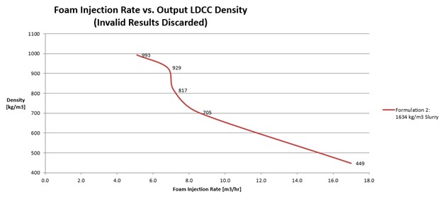
Figure 1. Foam Injection Rate vs. Output LDCC Density
In this test, the slurry was studied with and without admixtures (e.g., flyash) and compressive strength tests were conducted to determine the influence the admixtures had on the strength of the cured LDCC. Based on the compressive strength results of the first phase of testing, which showed that flyash has adverse effects on compressive strength, a simple Portland Cement-and-water slurry at a water-to-cement ratio of 0.6 without admixtures was selected as the base slurry mix design.
Due to the ratios of the constituents of the slurry (6 parts water to 10 parts cement), the slurry density was nominally 1746 kg/m^3 [109 Pounds per Cubic Foot (PCF)]. Compressive strength cylinders were obtained for each distinct LDCC density created with the 0.6 water-to-cement slurry and subsequently tested at an accredited testing lab in accordance with relevant ASTM standards. LDCC densities which produced acceptable results regarding minimum compressive strength requirement and minimum air entrainment ranged between 480 kg/m^3 [30 PCF] and 961 kg/m^3 [60 PCF]. The compressive strength test results demonstrated an inverse correlation between porosity (achieved by the increase in foam in the LDCC to produce a lower density) and compressive strength.
Test Phase 2
To optimize the void filling efficacy of grout, the second phase of testing focused on how the LDCC density influences the flowability of the LDCC. This was accomplished by conducting several levelness tests (Figure 2) with grout of varying densities – 720 kg/m^3 , 849 kg/m^3 , and 961 kg/m^3 [45 PCF, 53 PCF, and 60 PCF].
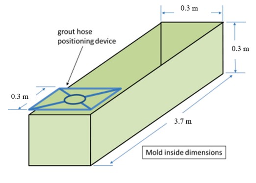
Figure 2. Model of Constructed Form for Levelness Test
The results (Figure 3) demonstrate a positive correlation between density and flowability, with 961 kg/m^3 [60 PCF] having the best performance. Since 961 kg/m^3 [60 PCF] LDCC approaches the lower limit of the minimum air entrainment requirement while showing little increase in degree of flowability compared to 849 kg/m^3 [53 PCF], 849 kg/m^3 [53 PCF] was chosen as the LDCC density. This LDCC density demonstrated an optimized balance of the design requirements (minimum compressive strength and flowability) while still maintaining an adequate margin regarding minimum air entrainment.
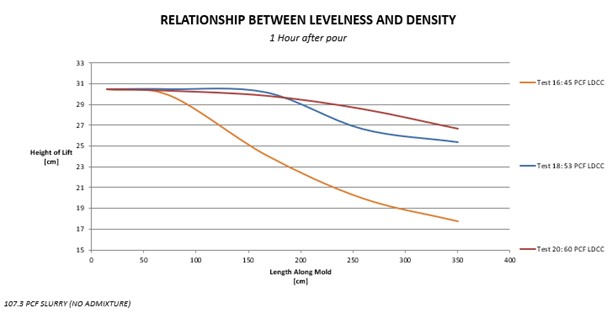
Figure 3. Levelness results of LDCC at Varying Densities
Test Phase 3
Once the mix design of the slurry and the subsequently produced LDCC was refined, the third phase of testing focused upon the performance of 849 kg/m^3 [53 PCF] LDCC while void filling the RVI. To accomplish this, detailed mockups were designed to mimic RVI components which featured the most geometrically restrictive flow paths the LDCC would encounter while filling the RV in a “bottom-up” fashion, shown in Figure 4. The mockup tests demonstrated that the continuously delivered grout infiltrates and completely fills void spaces through any given cross section in an upward fashion.
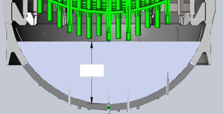
Figure 4. RV Bottom-Up Fill Method (Grout shown in blue)
The RVI components to be studied in mockup testing comprised of the Lower Internals Assembly (LIA) (Figure 5) and the Plenum Assembly (PA) (Figure 6). Detailed Computer Aided Drafting (CAD) models of these components were used as the design basis for full scale mockups constructed out of wood and PVC piping.
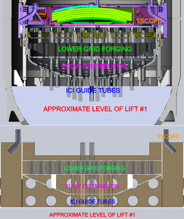
Figure 5. CAD Model of LIA (top) in Comparison with Mockup of LIA (bottom)
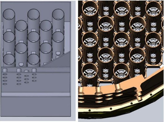
Figure 6. CAD Model of PA (right) in Comparison with Mockup of PA (left)
To further increase the fidelity of mockup testing, the on-site grout hose path from the FG to the RV was walked down and inspected to determine the total path length and changes in direction or elevation (Figure 7). This hose path was reproduced during mockup testing (Figure 8). In this way, the effects of increased flow path resistance on the wet density of the LDCC could be studied and understood.
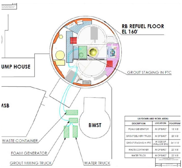
Figure 7. Grout Hose Path from Outside RB to RV
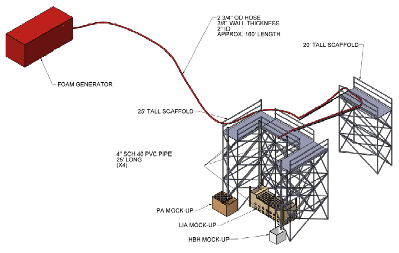
Figure 8. Simulated Grout Hose Path Layout for Mockup Testing
The results of the test showed that 849 kg/m^3 [53 PCF] LDCC has excellent performance in the void filling of both the LIA and PA mockups (Figure 9).
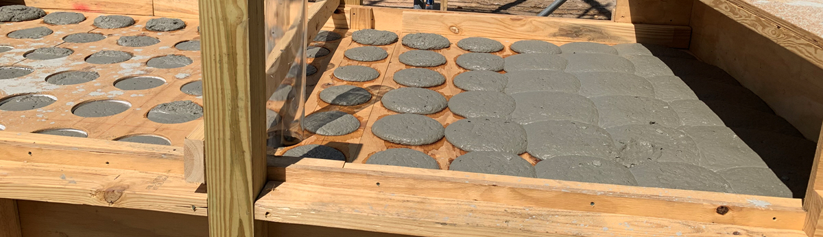
Figure 9. Bottom-Up Fill of Lower Grid Forging of LIA Mockup
However, it was noted that density samples obtained at the simulated elevation of the point of delivery differed consistently from the 849 kg/m^3 (53 PCF) LDCC delivered to the mockup, and some variability was noted between successive density samples at the mockup. It was concluded that damage was occurring to the wet LDCC upon impact due to the drop height from the point of delivery to the mockup, and that the control system of the FG was creating fluctuations in injection rates which adversely impacted the reliability of the system.
Test Phase 4
Having verified the performance of the mix design of the LDCC in void filling RVI components, the focus of Test Phase 4 was to increase the reliability of output of the FG system with respect to LDCC density. Data was also collected which related variable drop heights to the measured density increase of the LDCC before and after the drop. To achieve better system reliability, the FG was operated in manual mode, disabling the control system and minimizing the oscillations about the setpoint which are inherent to close loop feedback control systems. In manual mode, the injection rates of the air, water, and foam concentrate (the three components of preformed foam) are set independent of each other, as opposed to the automatic mode operation in which a foam flow rate is defined. Based on the results of Test Phase 3, the water and foam concentrate were also pre-mixed at a 40:1 ratio into the mixing water tank, thereby eliminating the need of the foam concentrate injection system and simplifying the production process overall. The injection rates of the air, water, and foam concentrate were defined by the following equations:
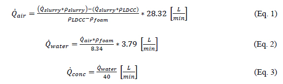
Since the water and concentrate are premixed together, the calculated flow rates of water and concentrate are simply summed, and the result is used as the flowrate for the water-and-concentrate mixture flowrate. These equations were then input into an Excel table to generate combinations of injection rate setpoints based upon a range of acceptable initial slurry densities and LDCC target densities. The foam density was selected as 44 kg/m^3 [2.75 PCF] based upon previous test experience and was treated as a constant. Likewise, the flowrate of the slurry was determined for the nominal progressive cavity pump operation speed and was validated with a flowrate test using water. This enabled the calculated injection rates of air and water-and-foam concentrate mixture to be proportional to the flowrate of the slurry, and with consideration of the initial density of the slurry, allows for a specific LDCC wet density to be accurately and reliably achieved.
To correlate the variable drop height and the density increase upon impact of the LDCC, a testing apparatus was designed featuring scaffolding and pipes of varying lengths to be suspended from the scaffold that was representative of the elevation of the CR3 Fuel Transfer Canal (FTC) floor and RV flange. In this test, the FG setpoints were adjusted to achieve the 849 kg/m^3 [53 PCF] LDCC density at the outlet of a pipe of specific length and numerous samples were obtained to verify the stability of the output density. The flow path was then changed such that several LDCC samples could be obtained at elevation, and the difference between the average resultant density of the two sampling locations could be recorded. In this way, the increase in density of the LDCC for a given drop height could be accurately quantified for several distinct drop distances. The results were then plotted, and a regression equation was derived to determine the density that would correspond to 849 kg/m^3 [53 PCF] LDCC being delivered to the current lift height within the RV after compensating for the increase in density due to impact from the drop height (Figure 10).
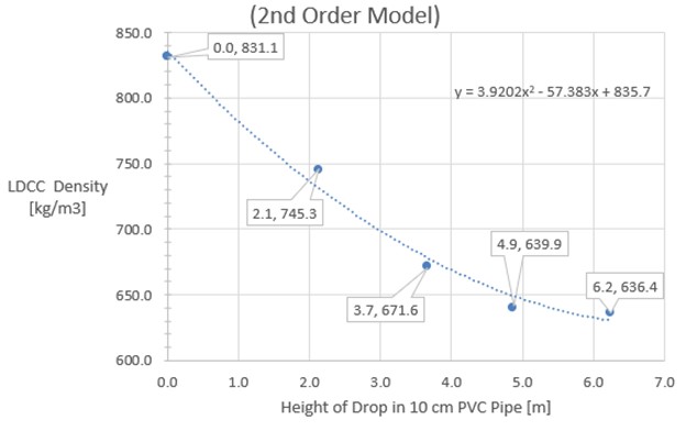 Figure 10. FTC Verification Density vs. Corresponding Drop Height
RV Grouting Operations
Upon successful completion of the testing phases and analysis of the collected data, the grouting system was ready to be commissioned and employed on site in the in-situ grouting of the CR3 RV. In the planning of the execution of CR3 RV grouting, the void fill volume was calculated using CAD models of the consolidated RV/RVI (Figure 11). The grouting of the RV was determined to be completed in five distinct “lifts” based upon the known volume of slurry that is delivered per cement truck, the number of cement trucks that could reasonably be made available in a day, and the expected yield of LDCC based upon the volumetric increase in output caused by the injection of foam into the slurry during the production of LDCC.
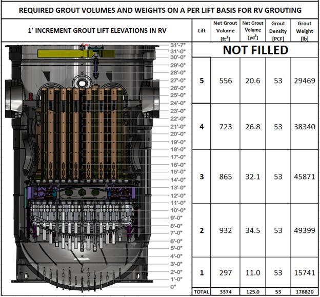
Figure 11. RV/RVI CAD Model with Grout Volumes and Weights on a Per Lift Basis
As defined in the testing site layout based upon on-site walkdowns and field studies, the FG was staged outside of the radiologically controlled area such that the hose path length, number of bends, and increases in elevation were representative of the conditions studied throughout the testing phases.
Using the data displayed in Figure 10 in tandem with the Testing and Qualification Process developed during the testing phases, the produced LDCC was iteratively tested on the FTC floor near the RV flange to ensure that the FTC verification densities were achieved prior to delivering grout to a given elevation within the RV. This process provided assurance that LDCC was delivered to the RV within the acceptable density tolerance of ± 80 kg/m^3 [5 PCF], as defined by ODS in a Grout Verification Procedure under the ODS Quality Assurance Program.
Due to the restricted access into the RV, the time duration of each lift was determined based on the calculated fill volume per lift and the expected flowrate of the produced LDCC. This was accurately determined by the flowrate test that was previously performed on the progressive cavity slurry pump and an applied correction factor based on the volume multiplication factor associated with producing 849 kg/m^3 [53 PCF] LDCC by mixing 44 kg/m^3 [2.75 PCF] foam with 1746 kg/m^3 [109 PCF] cement slurry. After each lift, the lift level was verified by measuring the distance from the RV flange to the exposed surface of LDCC within the RV, which was typically within 3 cm to 8 cm from the expected lift level. The systematic and precise delivery of specific volumes of LDCC to the RV was enabled by the use of stopwatches which tracked the time that LDCC was being delivered to the RV, with consideration to the expected time of delivery required based on the calculated lift volume and flowrate.
Stop watches were also used to track other important metrics such as the useful life of the slurry once mixed at the batch plant, as well as the consumption of slurry from the cement truck. Based on best practices established throughout the testing process, the slurry was assigned a two-hour useful life once the water and cement were mixed at the batch plant. Similarly, only the first six cubic yards of the seven-cubic yard cement truck load was to be used per cement truck, as this mitigates the potential of introducing residual aggregate from a previous load into the hopper of the FG and damaging the progressive cavity pump. An upper temperature limit (35 °C [95 °F]) was also imposed upon the slurry mixture to ensure that flash setting had not occurred and that the slurry mixture had a viscosity low enough to be pumped without putting excessive load on the FG pump and production system. This temperature limit was tested and verified prior to the commencement of pumping of each truck, as well as at the volumetric midpoint of each truck.
CONCLUSIONS
As a result of the strict application of the quality control methods and the thorough adherence to the engineering controls which were developed and delineated throughout the testing process, RV grouting operations were executed as planned and were successfully completed with a reliable and consistent LDCC mix design. The testing apparatuses and simulated environments were thoughtfully designed to mimic the environments, challenges, and processes that would be encountered and employed during on-site RV grouting operations. Because of this careful preparation, the commissioning and operation of the system encountered no off-normal or unexpected conditions which had not been previously identified and resolved during the testing phase, allowing for a timely completion of project deliverables according to the planned schedule. The mix design of LDCC was effective at infiltrating and void-filling the smallest voids present within the consolidated RV/RVI (Figure 12) and had excellent performance during RV segmentation with the diamond wire saw system, enabling three distinct segments to be produced which are now on-site awaiting shipment via barge to the final disposal site.
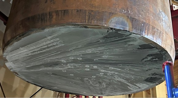
Figure 12. The Lower Cut Surface of the Middle Segment of the Consolidated RV/RVI
Throughout the RV grouting process, the base slurry mix design was strictly specified, controlled, and monitored. By operating the FG in manual mode, the volumetric flowrate of slurry and preformed foam injection was tightly controlled during the production of the grout mixture. This process resulted in the final grout density being accurately and repeatably controlled such that it is an effective means of void filling highly contaminated and geometrically restrictive consolidated radioactive waste packages.
The successful completion of grouting the CR3 RV is the culmination of the rigorous research and development, testing and training, and qualification programs that ODS has completed. As a result, ODS has developed an expertise that goes far beyond the grouting of consolidated radioactive waste packages. ODS is in the unique position to plan out and place grout into RVs with repackaged wastes or any other large containments in compliance with requirements for transport and disposal.
>> Return to Orano White Papers